If you’ve ever had a simulation show the wrong tool geometry or found yourself digging through NC code just to figure out what tooling is actually in the program, the CIMCO Edit Tool Manager is going to make your life easier. It’s the central hub for defining, organizing, and verifying your tool assemblies, and it ties directly into both Backplot and Machine Simulation.
Here’s a rundown of what it is, how it works, and why it’s worth using.
What is the Tool Manager?
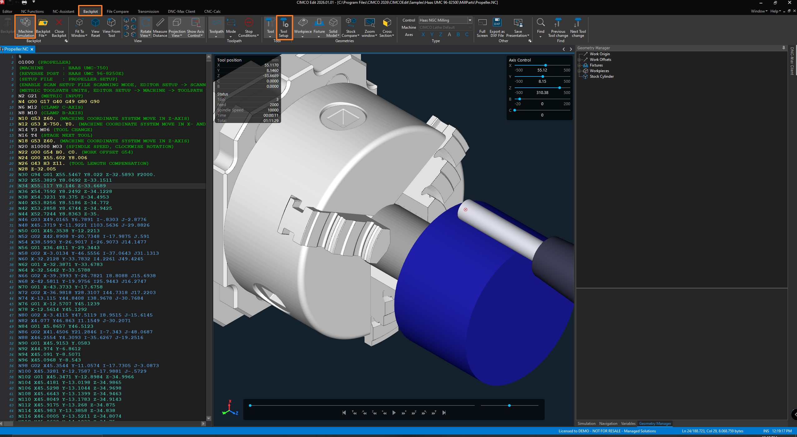
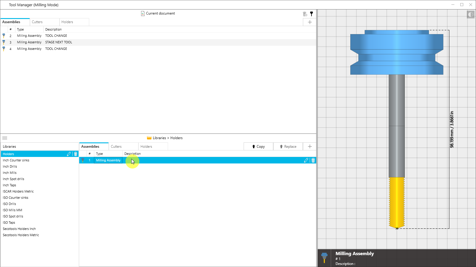
The Tool Manager lives inside CIMCO Edit and opens from the Backplot tab under Tools > Tool Setup. It gives you one place to manage all the tooling tied to your NC programs – cutters, holders, and complete assemblies – and connects that data straight to your simulation.
The window is split into three areas:
- Tools in Current NC Program. The top section shows whatever tools CIMCO Edit has found in your active program. These are what drive your simulation.
- Tool Libraries. The bottom section is where your tool libraries live, including the predefined ones that come with CIMCO and any custom libraries you’ve put together. Moving tools between libraries and your active program is quick and easy.
- Tool Preview. A live 3-D preview on the right updates as you click around, so you always know exactly what you’re looking at.
Assemblies, Cutters, and Holders
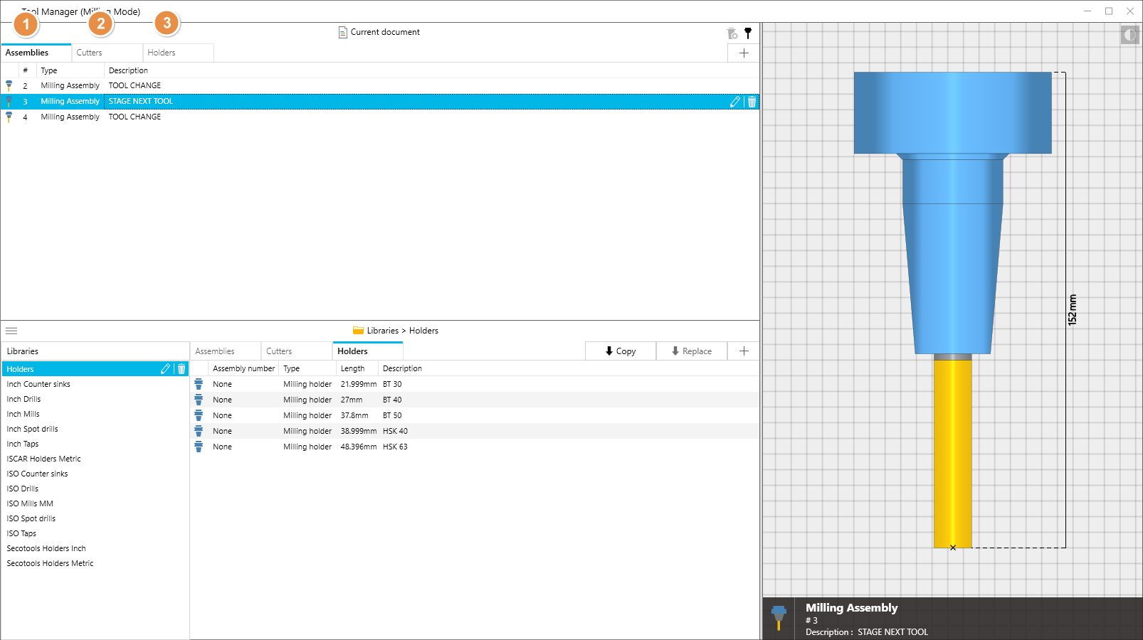
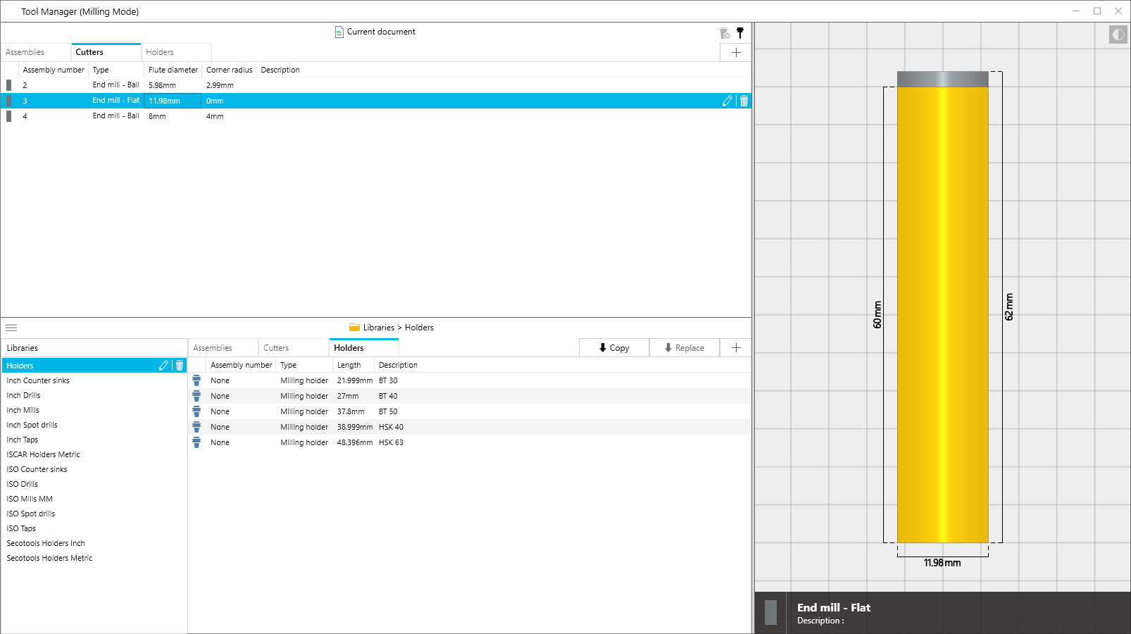
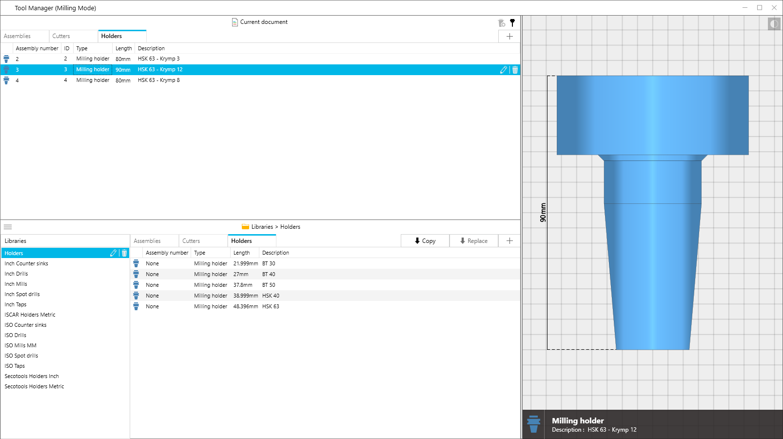
Tooling in the Tool Manager is broken into three levels, each with its own tab.
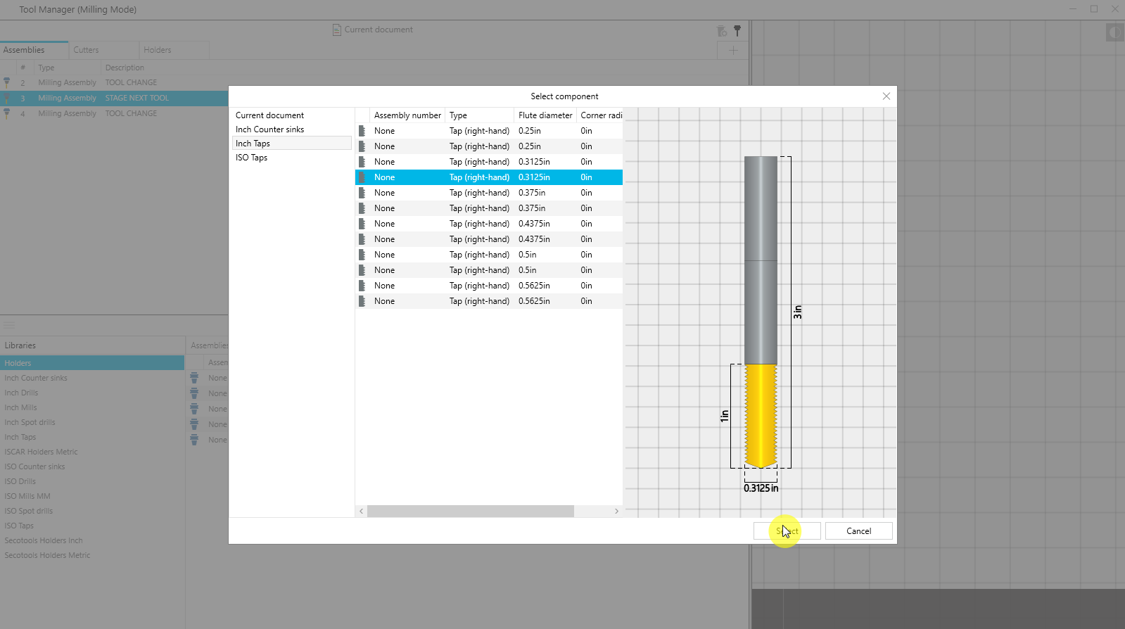
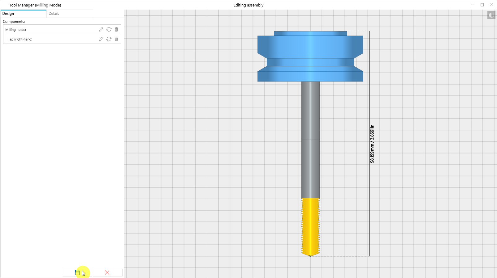
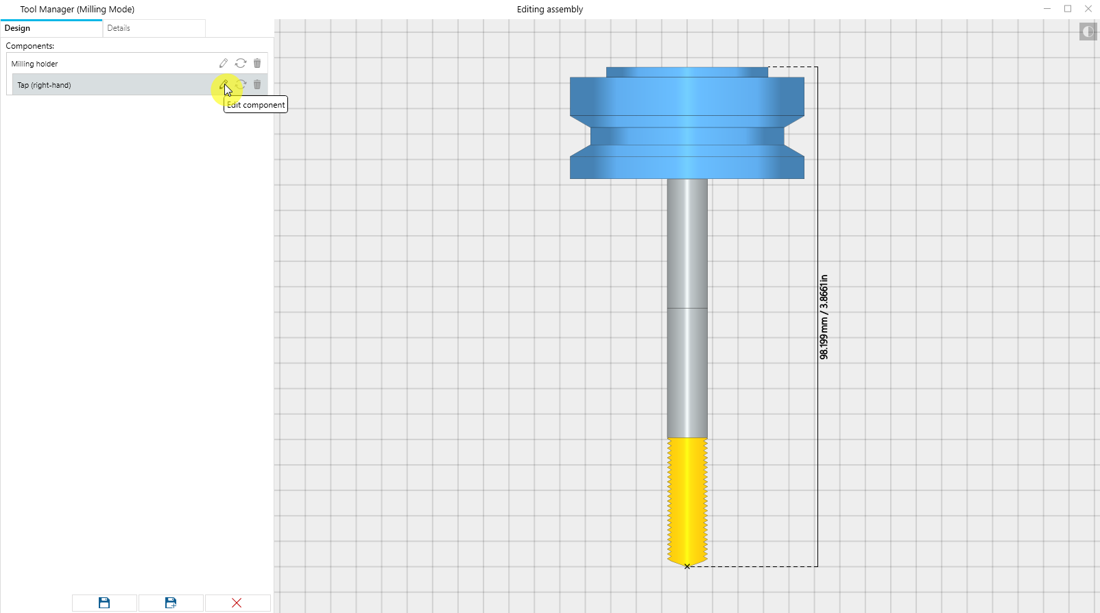
- Assemblies are the complete package. A cutter paired with a holder. This is what shows up in your simulation and what gets checked for collisions.
- Cutters cover everything that touches the workpiece: end mills, drills, turning inserts, probes, you name it. Editing one is pretty intuitive. You click directly on a segment in the 3D preview and the related parameter fields highlight automatically. Click the same segment again and it cycles through to the next parameter. For milling tools you’re working with things like flute diameter, flute length, shoulder, and body length. Turning inserts switch to their own set of options automatically.
- Holders work the same way. Milling holders are built from a stack of segments, each defined by an upper width, lower width, and length. Turning holders have their own type-specific parameters. Either way, the preview updates live as you make adjustments.
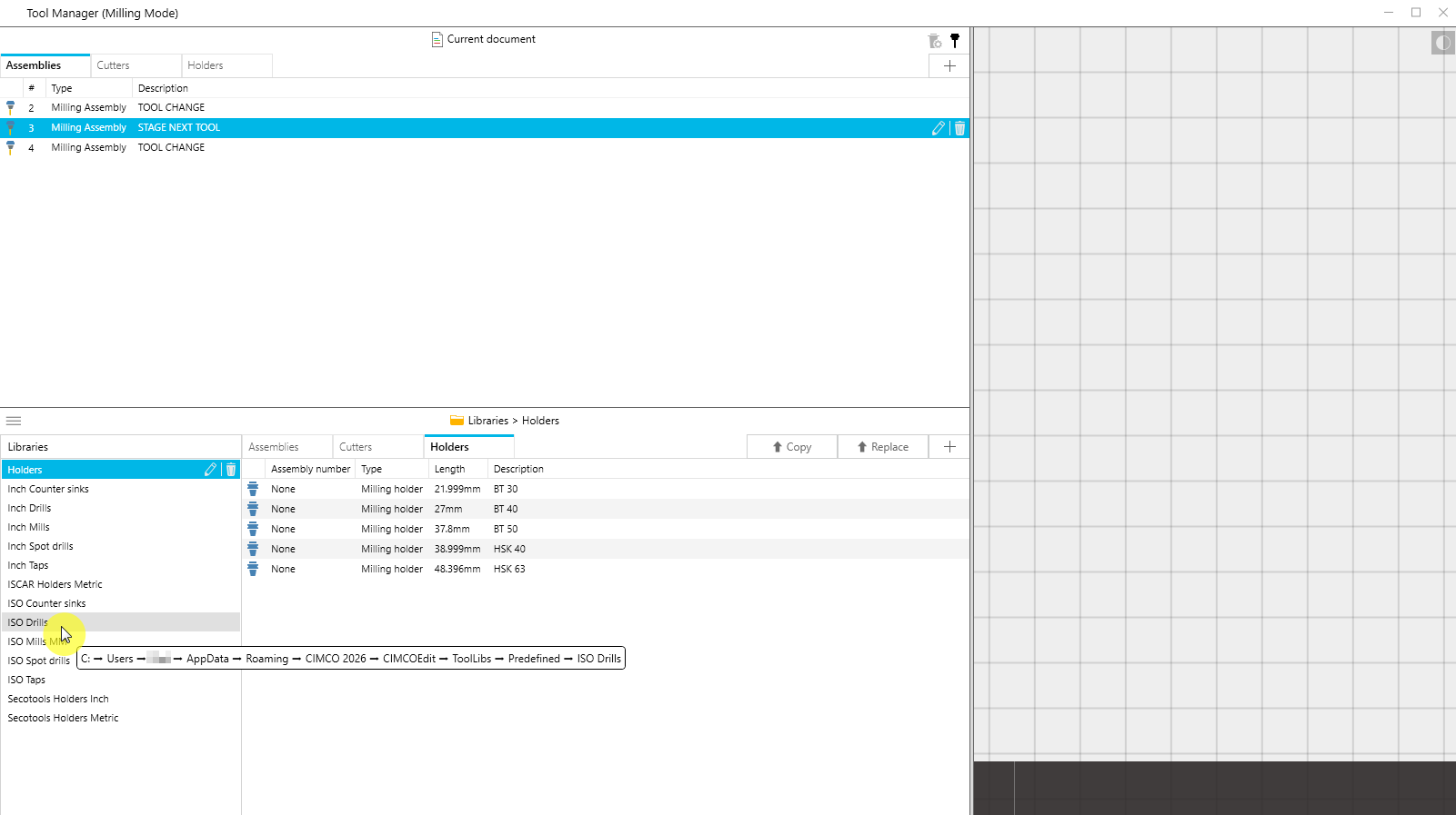
Tool Libraries
Libraries are stored in the CIMCO install folder and you can browse, rename, or check their file path right from within the Tool Manager. Hovering over a library in the list shows you exactly where it lives on disk.
Copying tools between a library and your current program is a single click, and the directional arrow on the copy button flips automatically based on what you have selected, so you don’t have to think about which way the transfer is going. There is also a Replace function that swaps a library tool into your current program while keeping the original tool number intact. Really handy when you’re standardizing tooling across multiple programs.
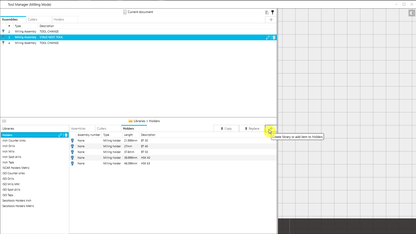
Creating Tools
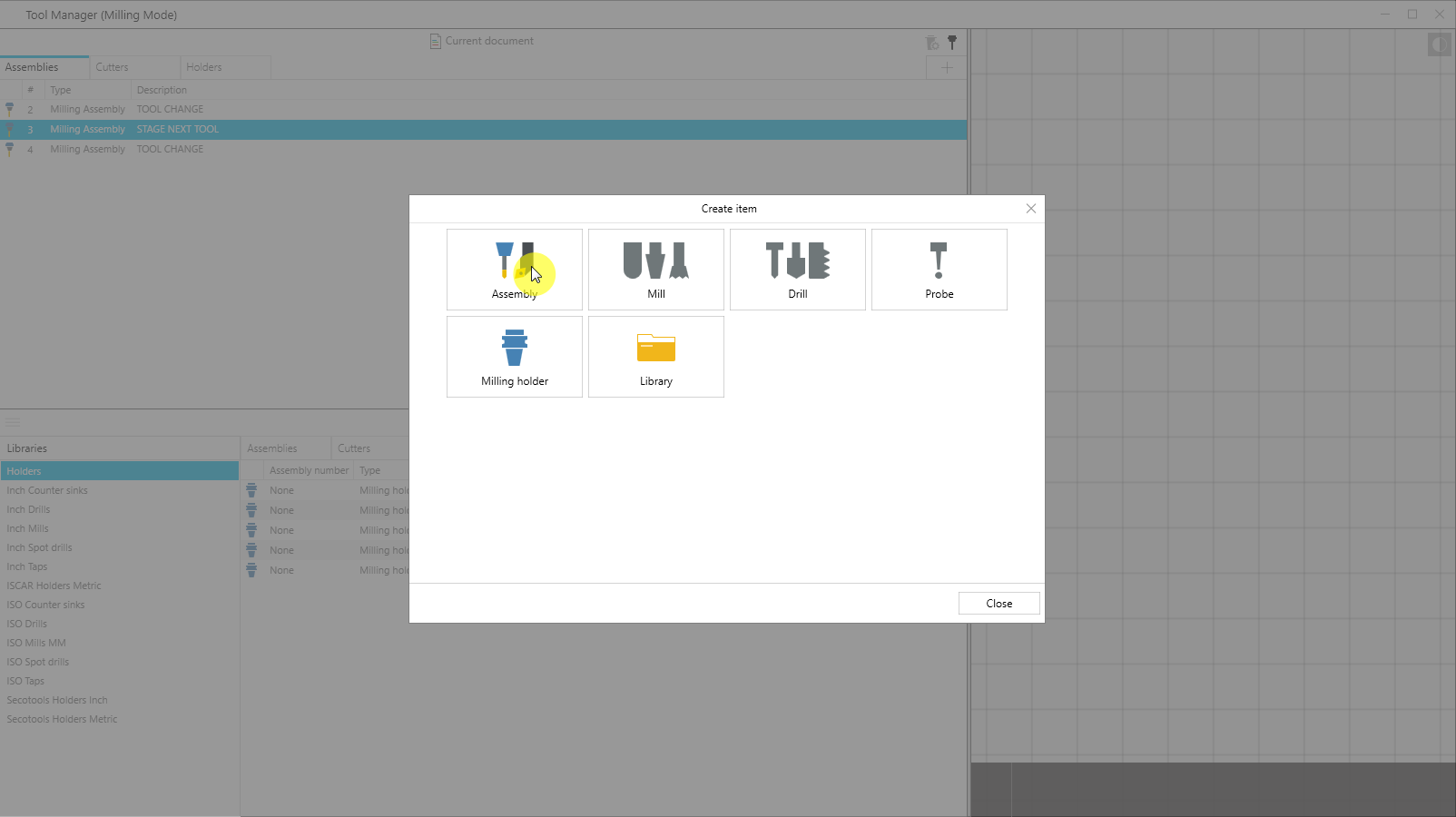
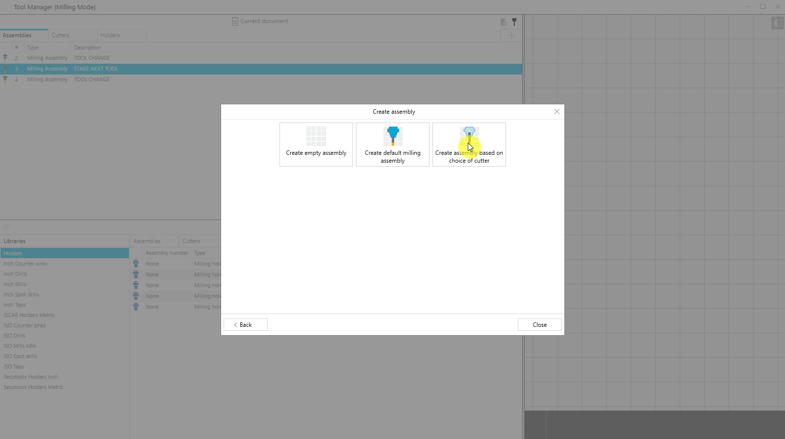
You can build new tools from scratch right inside the Tool Manager. The Create Item dialog walks you through picking what you want – assembly, cutter, holder, or a specific type like a milling tool, drill, or turning insert – and then shows you just the fields that are relevant to that item. No digging through options that don’t apply.
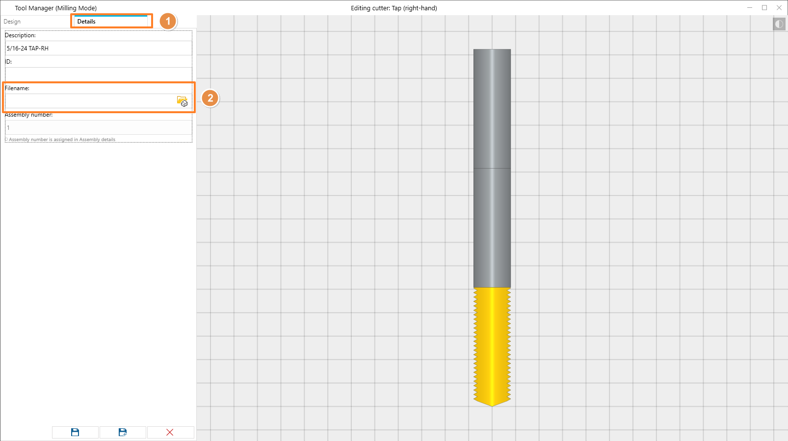
Once you’ve built something, you can give it a description and a custom ID so it’s easy to find in your lists and libraries later.
STL Models for Visual Fidelity
If you want your simulation to look more like your actual tooling, both the cutter and holder editors let you attach an STL file. Once you’ve assigned an STL to both the cutter and holder in an assembly, the simulation will render those models instead of the standard parametric geometry.
Worth noting: CIMCO still uses the configured parameters, not the STL, for collision detection. The STL is purely cosmetic.
Saving Your Work
This one trips people up occasionally, so it’s worth calling out. Changes you make in the Tool Manager show up in your simulation right away while it’s running. But they aren’t saved automatically.
To actually save your tool configuration, close the Tool Manager, then right-click anywhere in the Geometry Manager and hit Save Setup. By default it writes to a .setup file in the same folder as your NC program. You can also have it write the configuration directly into the NC program file itself. This is controlled by the Scanning settings in your Editor Setup.

Why it’s Worth Using
Simulation is only as useful as the data behind it. If your tools are defined incorrectly, then your clearance checks are wrong, your collision results are unreliable, and what you see on screen doesn’t match what’s going to happen on the machine. The Tool Manager gives you a practical, visual way to keep your tooling accurate, both for individual programs and across a reusable library you can build up over time.
For anyone already running Backplot or Machine Simulation in CIMCO Edit, it’s one of those features that’s easy to overlook but makes a real difference once you’re using it properly.
Want to Learn More?
The Tool Manager is already included in CIMCO Edit, no extra license needed. If you’d like help setting up your tool libraries or getting your simulation tooling dialed in, the team at Managed Solutions is here to help.
Whether you’re just getting started with CIMCO Edit or looking to fine-tune an existing setup, we can walk you through it. Reach out and let’s talk.